
Design

Typography as tooling: designing signage for CNC

Why letterforms need to be designed around the cutter, not the other way round.

Author
DraftEdge Engineering
Published
Jul 24, 2026
Updated
Aug 2, 2026
Read time
4 min
Difficulty
Beginner
Typography as tooling: designing signage for CNC

Share

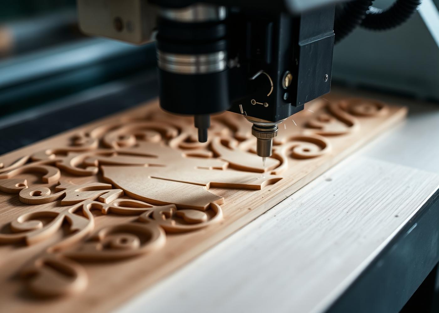
A typeface that looks crisp on screen can be physically impossible to cut. The cutter has a radius; the letter has to accept it.

Three constraints that decide the typeface

  • Minimum stroke width must exceed the cutter diameter, ideally by 1.5×.
  • Counters in a, e, o must clear the tool or they close up into blobs.
  • Sharp interior corners become radii — pick a face where that reads as intentional.

Cutter selection by letter height

Letter heightCutterMin. strokeStrategy
25–50 mm1.5 mm 2F2.5 mmProfile + tab
50–150 mm3.175 mm 2F5 mmPocket + profile
150–400 mm6 mm 2F9 mmAdaptive pocket
Any (incised)60° V-bitn/aV-carve

Frequently asked

Best material for exterior signage?

Marine-grade HDPE or powder-coated aluminium. Both hold edges and survive UV without refinishing.
Downloads

Engineering assets that accompany this article. Free to use on commercial work with attribution.

  • STL

    Print-ready mesh

    6.1 MB

  • DXF

    2D profile for laser / router

    480 KB

  • PDF

    Dimensioned drawing set

    1.1 MB

References

  1. [1]Vectric V-Carve reference — Vectric
#Signage#Typography#CNC Router#V-Carve#Fabrication
DE

Written by

DraftEdge Engineering

Mechanical Engineer · CAD Designer · CNC Programmer · Product Development · Manufacturing Engineering

We are a manufacturing-first engineering studio. Every model we release has been through CAM, tolerance review, and a first article before it reaches a client — which is why our writing reads like shop notes rather than software tutorials.

Discussion(3)

Comments are moderated before publication.

  • Marcus Hale

    Manufacturing Engineerjust now

    The datum-over-face rule alone would have saved us two weeks last quarter. We now enforce it in our model review checklist.

    • DraftEdge Engineering

      Authorjust now

      That matches what we see. The failures are almost never exotic — they are a sketch plane on a fillet.

  • Priya Raman

    Design Engineerjust now

    Curious how you handle derived CAM bodies across a 200-part assembly — does the derived file strategy still scale there?

All articles
Newsletter

Stay Ahead in Engineering

Engineering articles, CAD tutorials, CNC workflows, manufacturing insights, product design tips, and technical resources — delivered to your inbox. No spam, unsubscribe anytime.

Need CAD Design or Manufacturing Support?

DraftEdge Engineering provides CAD modeling, CNC programming, product development, manufacturing consulting, mechanical design, prototyping, and end-to-end engineering solutions.