CNC

Toolpath finishes that survive first article inspection

Stepover, engagement, and entry strategy decide whether a surface passes inspection — or gets polished by hand at 2 a.m.

Author
DraftEdge Engineering
Published
Sep 18, 2026
Updated
Sep 30, 2026
Read time
6 min
Difficulty
Advanced
Toolpath finishes that survive first article inspection

Share

First article inspection does not care how fast you cut. It cares whether the surface, the size, and the geometry repeat. Most finishing failures trace back to three parameters set by habit rather than by calculation.

Scallop height is a decision, not a default

Formula

h = R − √(R² − (s/2)²)

Scallop height h for a ball mill of radius R at stepover s.

Work backwards from the required Ra rather than accepting the CAM default. A 6 mm ball mill at 0.25 mm stepover leaves roughly 2.6 µm of cusp — acceptable for a bracket, unacceptable for a sealing face.

Finishing parameters by material

MaterialToolSpeed (m/min)Feed/toothStepoverTypical Ra
6061-T6 aluminium3F carbide, AlTiN300–4500.06 mm8% Ø0.8 µm
7075-T6 aluminium3F carbide, polished250–4000.05 mm6% Ø0.6 µm
304 stainless4F carbide, coated80–1200.04 mm5% Ø1.2 µm
Ti-6Al-4V5F carbide, high helix40–700.03 mm4% Ø1.6 µm
Acetal (POM)2F uncoated400–6000.10 mm10% Ø0.9 µm
Starting values for rigid setups; reduce 30% on long-reach tooling.

Constant engagement beats high feed

  • Trochoidal and adaptive paths hold radial engagement steady, so deflection stays constant and the wall stays straight.
  • Corners are where engagement spikes — let the CAM slow the feed rather than the operator slowing the whole program.
  • Climb mill finishing passes without exception; conventional milling burnishes and work-hardens.
gcode
G0 X-12.500 Y0.000 Z5.000
G1 Z-8.000 F400.
G3 X0.000 Y-12.500 I12.500 J0.000 F1200.  ; arc lead-in
G1 X40.000 F1600.                          ; finishing contour
G3 X52.500 Y0.000 I0.000 J12.500          ; arc lead-out
G0 Z25.000
Tangential arc lead-in on a finishing contour

Before you press cycle start

  • Tool stickout measured and entered, not estimated
  • Semi-finish stock uniform on walls and floors
  • Lead-in and lead-out arcs on every inspected surface
  • Coolant reaching the cut, not the shroud
  • Probe cycle confirming datum before the finishing operation

Frequently asked

Ball mill or bull nose for floors?

Bull nose. It leaves a flatter floor with a larger effective cutting diameter and far less cusp.

How much does stickout really matter?

Deflection scales with the cube of stickout. Reducing it by 20% roughly halves deflection.
Downloads

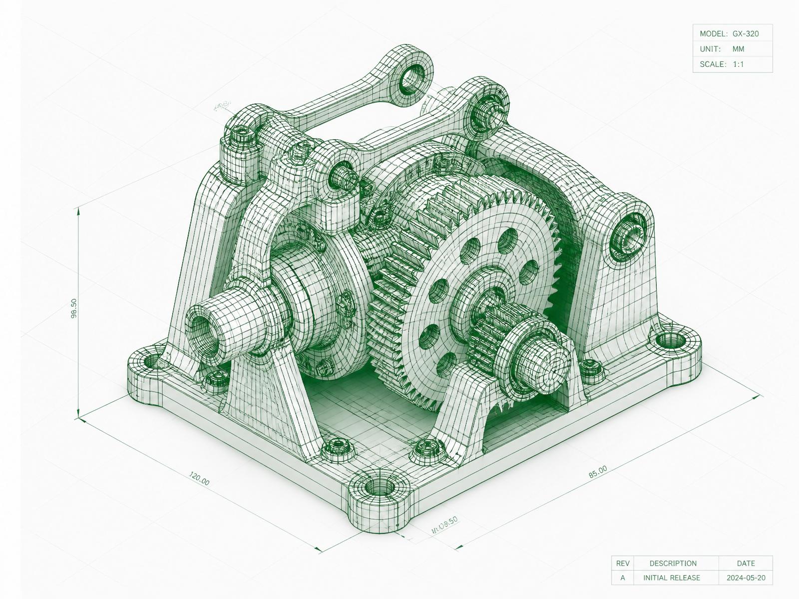
Engineering assets that accompany this article. Free to use on commercial work with attribution.

  • SLDPRT

    Reference part — parametric master model

    4.2 MB

  • STEP

    Neutral geometry exchange file

    2.8 MB

  • STL

    Print-ready mesh

    6.1 MB

  • DXF

    2D profile for laser / router

    480 KB

References

  1. [1]ISO 4287 — Surface texture parameters — ISO
  2. [2]Sandvik Coromant technical guide — Sandvik
#CAM#Surface Finish#Toolpaths#Inspection#Aluminium
DE

Written by

DraftEdge Engineering

Mechanical Engineer · CAD Designer · CNC Programmer · Product Development · Manufacturing Engineering

We are a manufacturing-first engineering studio. Every model we release has been through CAM, tolerance review, and a first article before it reaches a client — which is why our writing reads like shop notes rather than software tutorials.

Discussion(3)

Comments are moderated before publication.

  • Marcus Hale

    Manufacturing Engineerjust now

    The datum-over-face rule alone would have saved us two weeks last quarter. We now enforce it in our model review checklist.

    • DraftEdge Engineering

      Authorjust now

      That matches what we see. The failures are almost never exotic — they are a sketch plane on a fillet.

  • Priya Raman

    Design Engineerjust now

    Curious how you handle derived CAM bodies across a 200-part assembly — does the derived file strategy still scale there?

All articles
Newsletter

Stay Ahead in Engineering

Engineering articles, CAD tutorials, CNC workflows, manufacturing insights, product design tips, and technical resources — delivered to your inbox. No spam, unsubscribe anytime.

Need CAD Design or Manufacturing Support?

DraftEdge Engineering provides CAD modeling, CNC programming, product development, manufacturing consulting, mechanical design, prototyping, and end-to-end engineering solutions.